Build
Ramp
Coink is actually very easy to build. First we need the ramp to insert the coins. The ramp is a 3D design that can be very easily printed with any FDM 3D printer (or any other more-advance 3D printer if you have access to it).
The 3D design is very simple but, in turn, we need to do some work before using it. First, we need to glue some plastic sheets to cover the inner parts of the ramp. This way we avoid the coin bumping into any disturbances around the sensor board, where the ramp is not continuous:
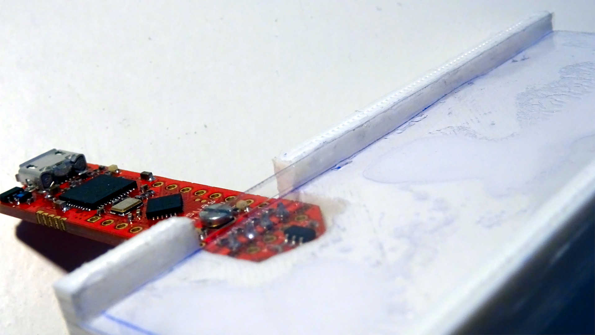
Plastic sheets covering the inner parts of the ramp.
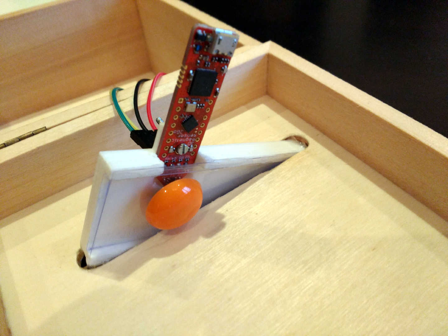
Then we need to cover the outter part of the ramp by glueing another plastic sheet. We will glue our magnet (in orange) there, just in front of the sensor board. Any magnet will do, we just need to make sure it is not too powerful, or the coins will get stuck in the ramp!
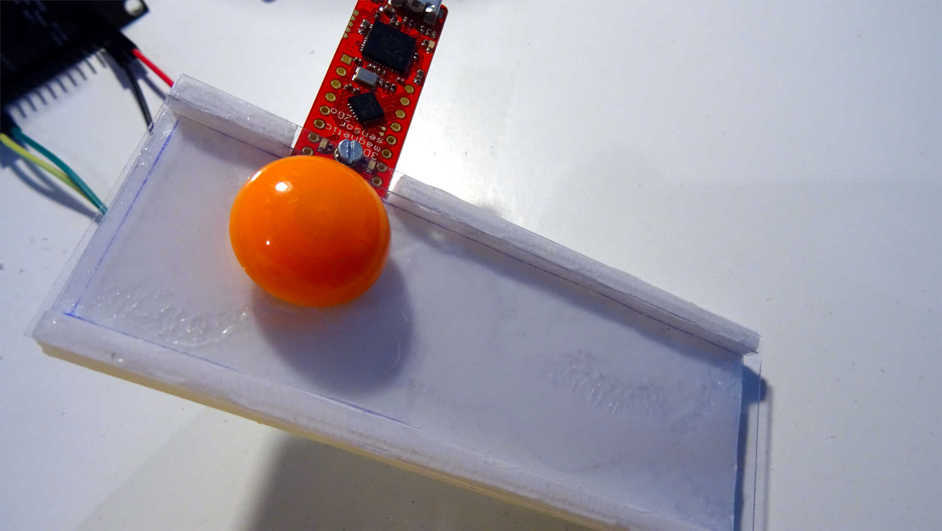
Plastic sheet covering the outter part of the ramp and magnet attached to it.
Box
The piggy bank can be made with a small wooden box. Wood is easy to work with, which is important as we will need to create a hole for the ramp in the box:
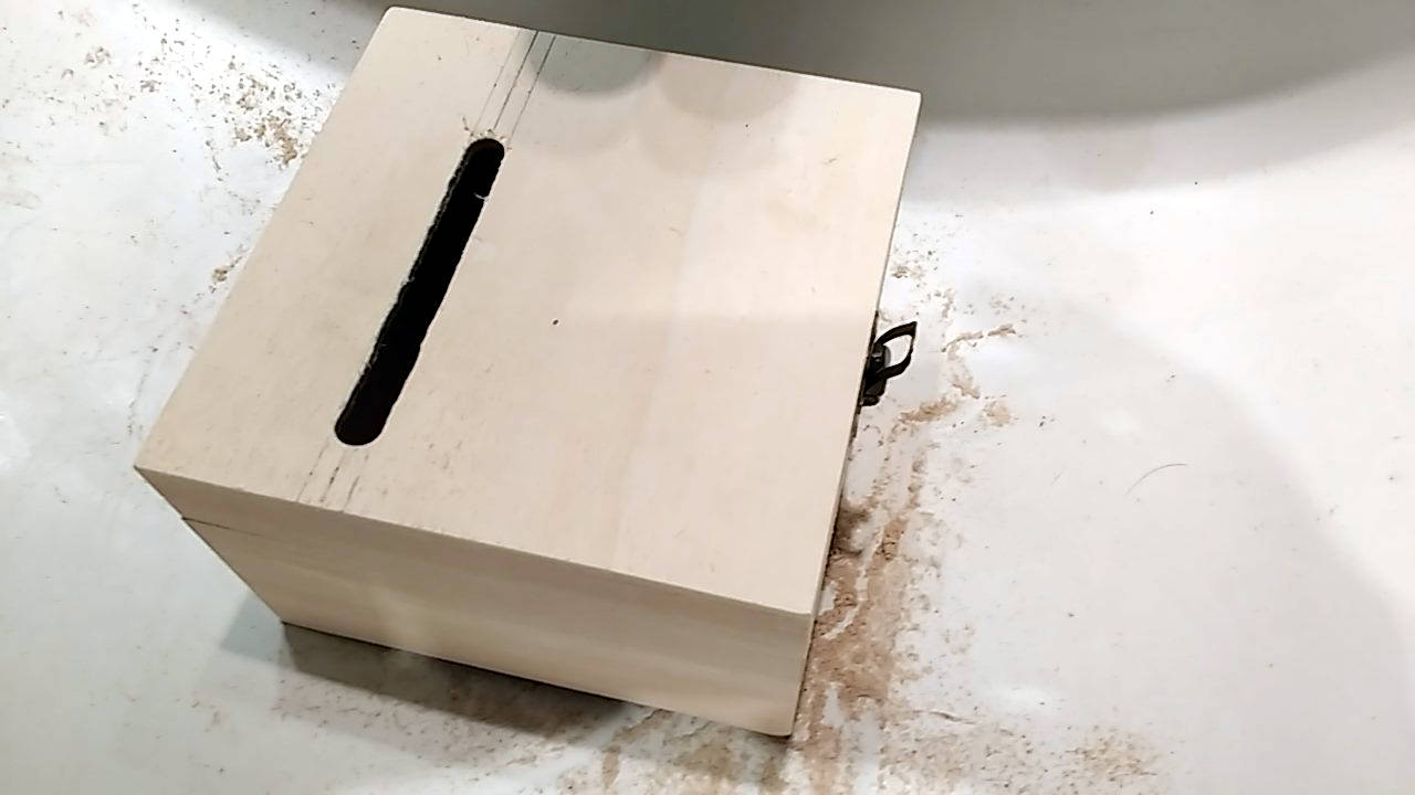
Wooden box with a hole for the ramp.
Once we have the hole, we can very easily glue the ramp to the box with some epoxy to make sure it does not move.
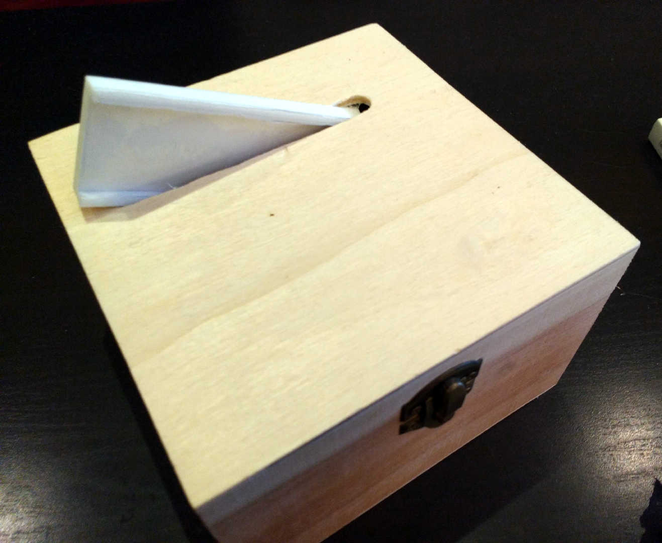
Ramp glued to the box.
Even if obvious, we should make sure the magnet and the magnetic sensor board both fit inside the box before glueing the ramp!
Detail of the ramp inside the box.
Once the ramp is fixed, we only need to stick the rest of the components to the lid:
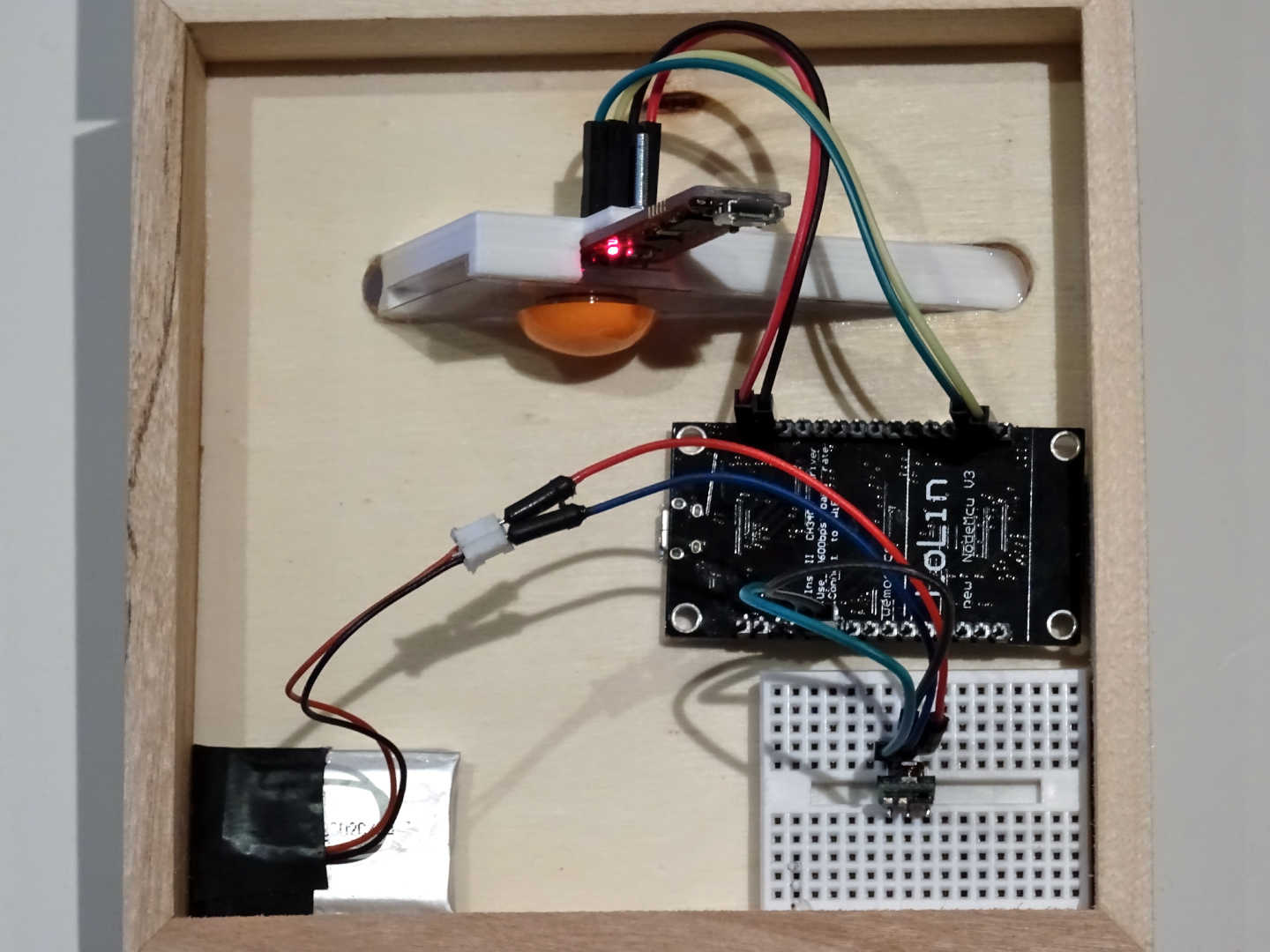
All the required components fixed and the system powered!
Note that we added a simple power circuit consisting of:
- A LiPo battery (single cell).
- A 3.3 V step-down DC-DC converter mounted on the breadboard.
The output of the converter directly powers the board at 3.3 V.
Wiring
Wiring the magnetic sensor board and the NodeMCU boils down to connect only 4 wires:
| NodeMCU pin | Magnetic sensor pin |
|---|---|
| D1 (GPIO5) | SDA (P2.10) |
| D2 (GPIO4) | SCL (P2.11) |
| 3V3 | 3V3 (P1.0) |
| GND | GND |
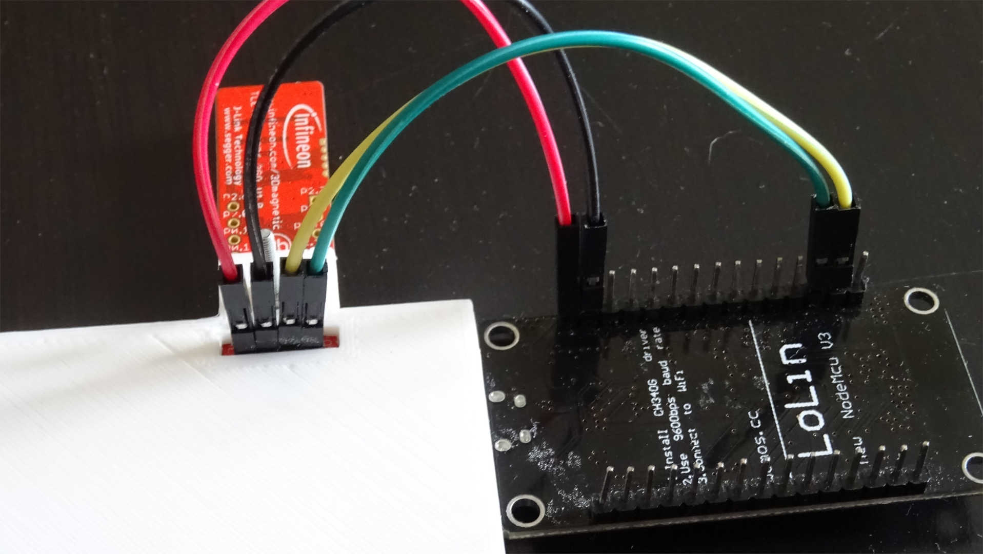
NodeMCU and magnetic sensor wiring.